STEM Detective Lab’s Slicer Software Investigation
3D Printing for Beginners Series
- A 3D Printer Overview
- 3D Modeling Options
- Slicer Software Explained
- Fun With Fusion 360
- Toying With Tinkercad
Welcome to Slicer Software Explained, the third section of our 3D Printing for Beginners series. In this section we will discuss:
- What slicer software is.
- Common terminology you should know when working with your slicer.
- Which custom settings are helpful when you’re first starting out.
- Common problems you may run into when printing your 3D model.
- Troubleshooting tips.
Note: All information discussed in this section will be for a Fused Deposition Modeling (FDM) printer. Consumers who are just starting out with their 3D printing hobby usually choose FDM printers. These printers are less expensive and they have the added benefit of having a better variety of filament available.
Slicer Software
As we first mentioned in our 3D Modeling Options segment, your 3D printer will not be able to understand your 3D model’s .stl file. You need to use slicer software to convert the .stl file into a set of instructions your printer can understand. The slicer will generate these instructions into a g-code file which is the programming language your printer can read. The quality of your print is at the mercy of your slicer software settings. The more familiar you are with them, the better your printing experience will be.
What you print, how fast you want to print it, and the quality of your finished print are all factors you can address in the slicer settings.
Getting Started
Your 3D printer will extrude melted thermoplastic onto its print bed layer-by-layer to create your 3D model. Before this can happen, you need to first properly set up your slicer’s print settings. Your slicer will use these settings as it divides your model into thin layers and generates the print instructions we previously mentioned.
These settings control print bed & nozzle movement, layer thickness & height, top & bottom thickness, print speed, fill density, and so much more. The following tabs break down the steps we recommend you follow to get the most out of your slicer software. Furthermore, we hope these steps answer your questions, and help you approach this process with excitement instead of hesitation.
Note: The slicer images throughout the examples below are from Ultimaker Cura, the slicer we use with our printer. Cura is popular, free, and easy to use. Plus they have excellent online documentation available in their Support section.
Open Slicer Software
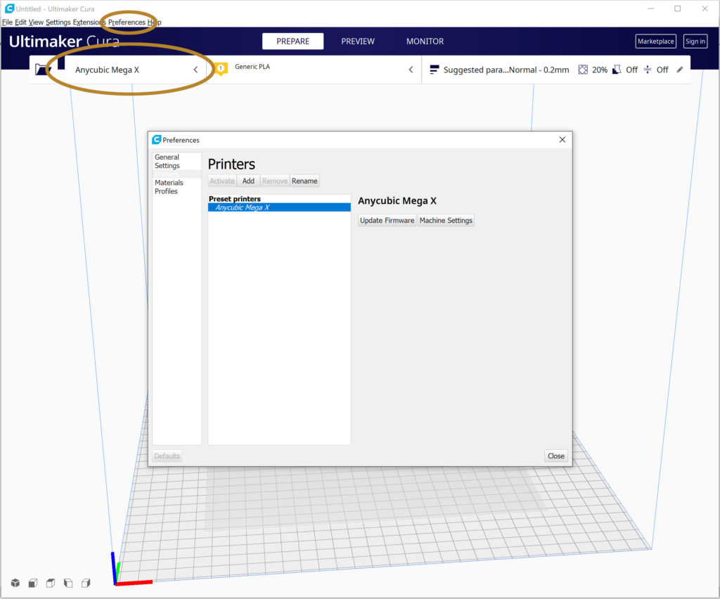
3D printers often come with a slicer recommendation because that slicer will already have a printer profile you can use. Using an existing profile will alleviate the stress of creating your own profile until you have more experience.
The first time you open your slicer, you may be asked to select your printer from an available list. If your printer isn’t on the list, check your printer’s website for additional information. You can also enter the printer information in your slicer’s printer configuration section.
As you can see in Figure 1, you can access Ultimaker Cura’s printer configuration through the Preferences menu or by clicking on the collapsible printer selection panel.
Open 3D Model Design File
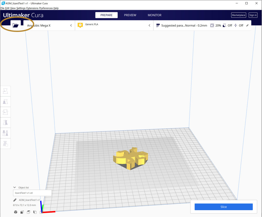
The 3D model’s design file is most often an STL file, but you may be able to use other file types such as OBJ, X3D, or 3MF depending on your slicer.
As you can see in Figure 2, you can open a file in Ultimaker Cura through the standard Open File option in the File menu, the Open folder icon, or you can drag and drop the file into Cura. You should then see your 3D model displayed on the 3D viewer’s print bed.
Quick Tools Location
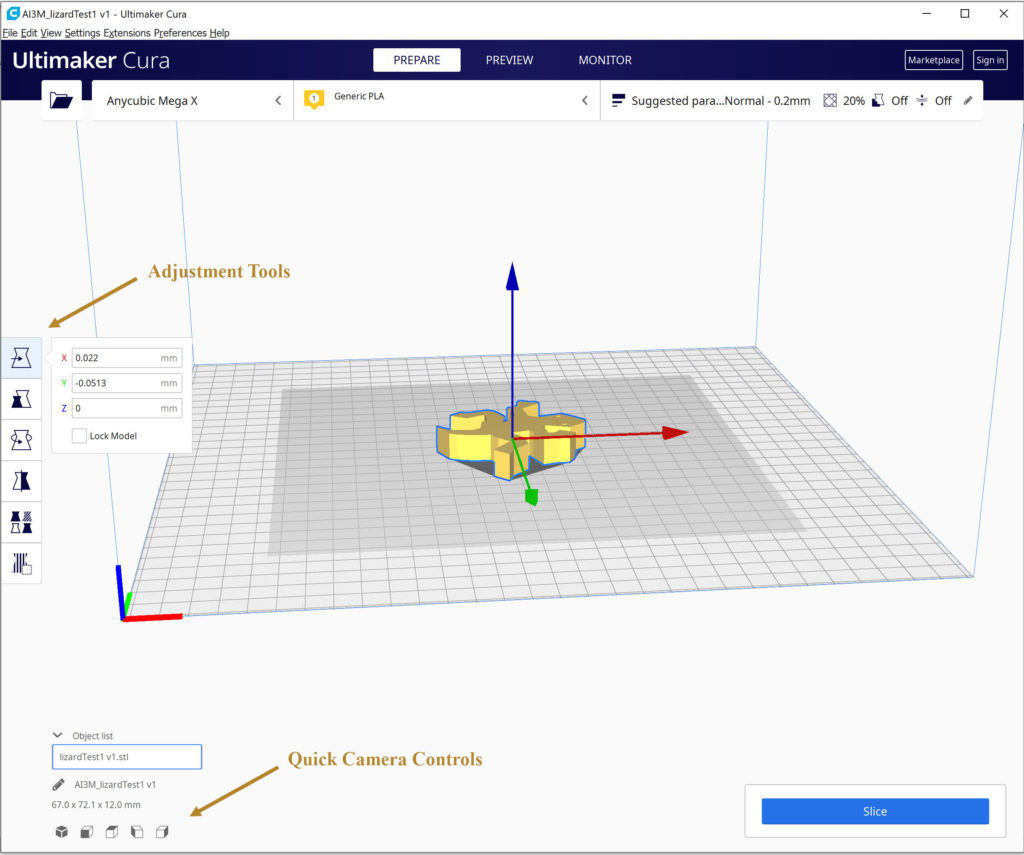
As you can see in Figure 3, Ultimaker Cura has two sets of quick tools that are worth noting – Their adjustment tools and their camera controls.
The adjustment tools located at the center-left edge of the Cura software are always visible, but only useable when you select your 3D model. These tools have a variety of uses, but the move, scale, and rotate features will allow you to maneuver your 3D model around the print bed in the 3D viewer.
The camera controls are accessible at any time and allow you to switch between several camera views – 3D, front, top, left, and right view.
Note: There are additional options available when you right-click on your 3D model. We particularly like the multiply option which is useful when you want multiple prints of your 3D model.
Modify Print Settings.
There are multiple settings you may want to change, depending on the 3D model you’re printing. Our more in-depth look at these settings in the tabs below will help you through your print setting modifications. The in-depth look below includes terminology you will run into, settings a 3D printing novice is most likely to change, and print issues that can be eliminated through your print settings.
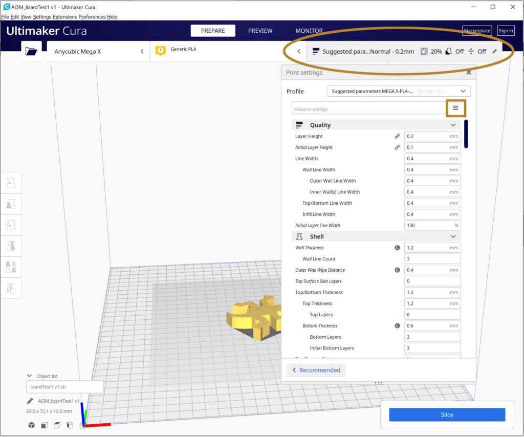
As you can see in Figure 4, you can access Ultimaker Cura’s print settings by clicking on the collapsible Print Settings panel where the most commonly used settings are listed by default.
You can manage these settings using the 3 line icon near the top right corner of the print settings list. You can also create a custom list using the settings list in the printer configuration area discussed in step 1.
Start Slicing Process
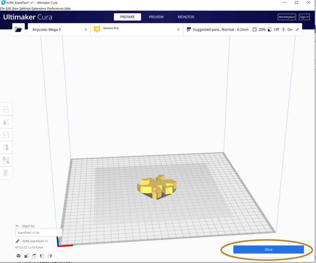
As you can see in Figure 5, the Slice button in Ultimaker Cura is located in the bottom right corner of the slicer software. Clicking the Slice button will start the slicing process and your slicer will ‘slice’ your 3D model design into horizontal layers based on the print settings you set up in step 4.
Don’t worry if you didn’t make any modifications to the print settings. The only modification we had to make on our first prints was adding a skirt around our 3D model. This allowed us to prime the printer’s nozzle before it started printing the actual model. This was particularly useful since our printer is in a cooler area.
Slicing Process Complete
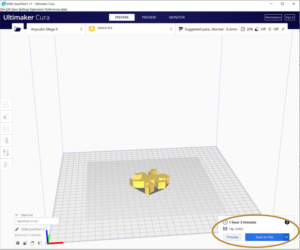
Once the slicing is complete, you should see information on the time it will take to print your 3D model, as well as the amount of filament the print will take. Keep in mind that these figures are estimations. You will also have the option to save the information to a file at this time.
As you can see in Figure 6, Ultimaker Cura displays this information in the bottom right corner where the Slice button was located.
Note: Before you save the generated instructions we recommend you preview the results of the slicing process.
Switch to Preview Interface
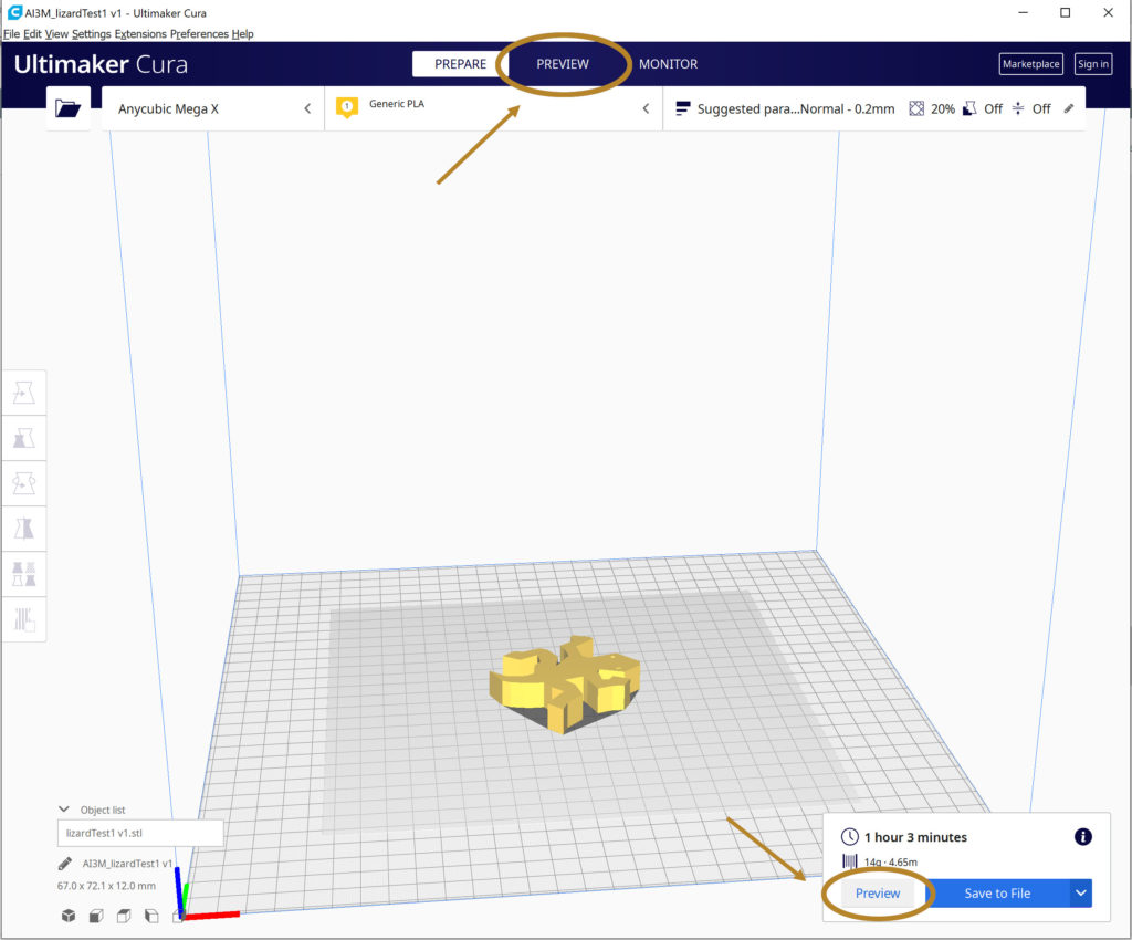
The preview step in the 3D printing process is one you should be sure to take advantage of. Previewing the result of the slicing process will give you the chance to spot any potential problems. It’s also a good time to make modifications to your print settings as you inspect the layer-by-layer printing process.
As you can see in Figure 7, you can preview the slicing results in Ultimaker Cura by clicking on the preview stage, located near the top center of the window, or by clicking on the preview action button at the bottom right corner. Either option will take you to Cura’s layer view.
Simulating the 3D Print Job
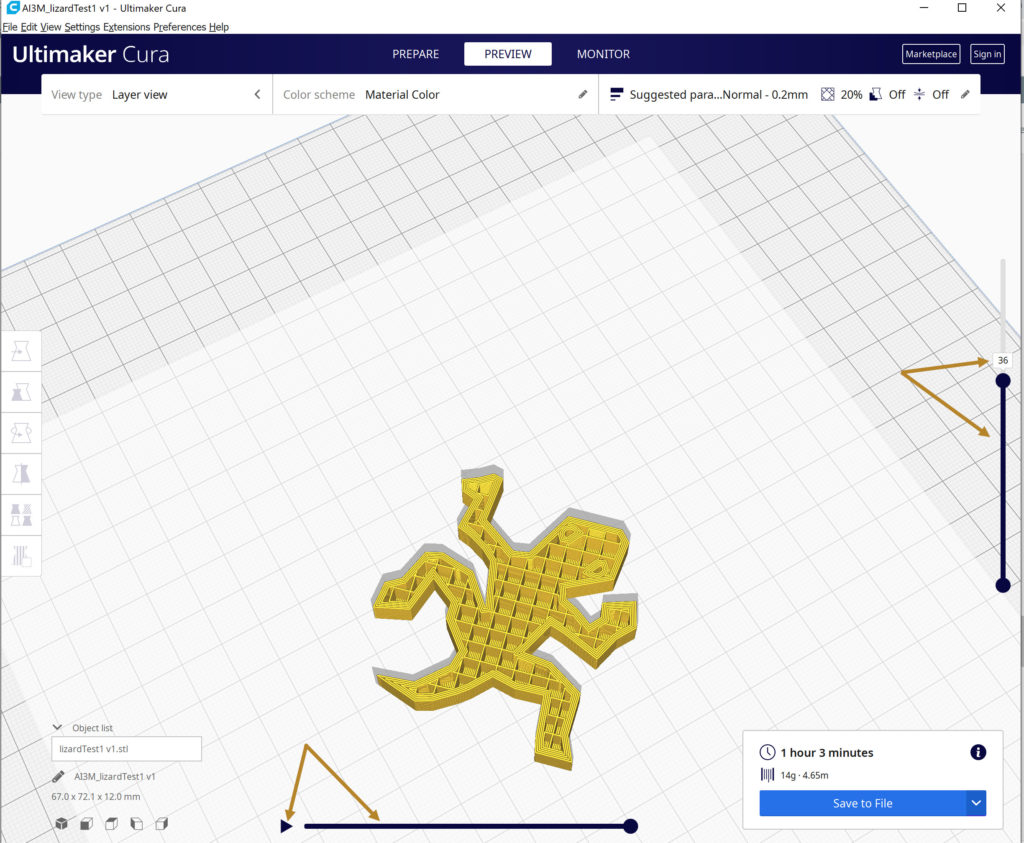
Although each slicer software package will have its own user interface, the basics should be the same. As you can see in Figure 8, Ultimaker Cura’s layer view provides two easy-to-use sliders. These sliders show what the inside of your model will look like as well as how it will be printed.
The layer slider runs vertically along the right side of the window. You can drag this slider up and down between your 3D model’s layers, or you can enter the number of a specific layer you’d like to see in the layer slider input box located just above this slider.
The path slider runs horizontally along the bottom of the window. Drag this slider back and forth to view the print path for the current layer selected or click on the simulation arrow to the left of the slider to see the print path of the model starting from the currently selected layer.
Head to Your Printer & Good Luck
The following three tabs are an in-depth look at print settings. The terminology, beginner-level settings, and troubleshooting discussions should help you modify your own settings as part of the Prepare Your Print phase above.
The development of 3D printing technology gave rise to a whole new set of technological jargon. Our list of 3D printing terms below consists of some of the more relevant terms you’ll see in your slicer software.
Print Quality
Skirt
A skirt is an outline of extra filament extruded on the print bed that surrounds your model but does not touch it. While similar to a brim, a skirt is only used to prime your extruder before your actual print starts, ensuring a steady flow of filament is available.
Brim
Similar to a skirt (defined below), a brim is a single layer outline of extruded filament attached to the base of the model being printed. But that’s where the similarity ends. Removed after printing is complete, a brim is meant to aid with bed adhesion, warping, and possible shrinkage of your printed model’s bottom layers.
Raft
A raft is one or more layers of filament extruded on the print bed that your model will be printed on. Like a brim, a raft is meant to aid with bed adhesion and warping, but a raft uses more filament, adds more time to your print, and is harder to remove at the end, so it’s better to use when a brim does not supply enough support.
Layer
Your 3D model will be printed as layers, one on top of another, each layer portraying a two-dimensional slice of your model within the X and Y plane. With the addition of each new layer along the Z plane, your 3D model is created.
Layer Height
The layer height determines the height, or thickness, of each layer to be printed. Thicker layers can speed up your print but at the sacrifice of finer detail. Additionally, the thicker layers will cause individual layers to be more visible.
Adaptive Layer Height
An adaptive layer height allows you to use thicker layers in low detail areas while keeping thinner layers where detail is needed. This allows you to speed up printing without sacrificing the finer detail.
Material
Shell
A shell is the exterior wall of your 3D model.
Shell Thickness
The shell thickness is the width of your 3D model’s exterior wall.
Infill
The infill is the filament extruded within the shell of your 3D model.
Infill Density
Measured in percentage, infill density is the amount of infill within the shell of your 3D model. A 0% infill density would create a hollow model while a 100% infill density would create a solid model.
Infill Pattern
The infill pattern is the structure or shape of the extruded infill. There are multiple pattern options and combined with the infill density, your pattern choice will help determine the strength and weight of your 3D model.
Overhang
An overhang is the section of a 3D model designed at an angle of 45 degrees or more with no support underneath.
Bridge
A bridge is a horizontal overhang located between two support structures.
Bridging
Bridging is the result of filament being extruded across an open area without the supports.
Support
A support is a structure built from the extruded filament in order to support any section of your 3D model that has no contact with a layer beneath it. These supports are removed after your 3D model has finished printing.
Support Materials
Support materials are materials used to support any sections of your 3D model that are designed at an angle of 45 degrees or more.
Movement Options
If you click anywhere on your 3D model you will have access to the following movement tools.
Move Tool
The move tool allows you to change where on the print bed your 3D model will be printed. Click anywhere on your model to highlight it
Rotate Tool
The rotate tool allows you to change the angle at which your 3D model will be printed.
Scale Tool
The scale tool allows you to increase/decrease the size of your 3D model.
With dozens of print settings available to modify and fine-tune, knowing where to start isn’t as daunting as you might expect. Your slicer may not have the same user interface as ours, but much of what’s available will be the same.
The modifications you may want to make are dependent on several factors. The shape and size of your 3D model, the type of filament you’re using, and the quality of print you’re looking for are just a few details to consider. Keep in mind, the more familiar you become with these settings, the better quality print you can create, and the more fun you will have.
Note: See our terminology tab for a more thorough description of the print settings below.
Layer Height
When you first start out, layer height is without a doubt, one of those settings you should pay close attention to.
A .1mm layer height is the lowest height we recommend when using the standard .4mm nozzle. This height offers the highest detail, but it will also take the longest time to print.
A .3mm layer height is the highest setting we would recommend with a .4mm nozzle. This height will cause the stair-stepping effect of layer lines to be more noticeable, especially on curved surfaces. However, it will reduce the amount of time your model will take to print.
You are not limited to the two heights listed above, but they show the optimum range you should use when getting started. A .2 mm layer height is a good combination between the overall print time and quality.
If you feel the need to go below .1mm or above .3mm, we recommend you look at investing in a new nozzle for your printer. Remember, the best layer height to use will depend on the needs of your 3D model.
Shell
The shell thickness value indicates how thick the exterior wall of your 3D model will be. This setting can be left at its default value for most prints, but you may have the occasional reason to modify it. If you are trying to get a stronger print, you can increase the thickness but this will also increase your model’s print time and cost as more filament will be used.
Infill Density
The infill density setting is another setting you can use to increase the strength of your print. This setting is measured as a percentage and it will vary depending on whether you’re printing something purely for aesthetic purposes, or if you’re working on an end-use part.
Unless you specifically want a hollow print, we recommend an infill density of 5% – 10% for aesthetic pieces and 25% – 30% if your piece is going to be used under some amount of stress. Like the shell thickness setting above, as the infill density increases, the cost and time of your print will increase too.
Support
Most slicers have an auto-generated support function that will look at the overhang angles your model has and extrude support structures where they’re needed. Generally, you can set up what angle to generate the support materials at. This value usually comes down to what your printer is capable of. A 50-degree angle is generally safe and you can adjust this value up or down as needed when testing.
Another support setting worth looking at is the “supports on build plate only” setting. When this setting is combined with auto-generate, your slicer will make sure the support material isn’t extruded on top of your model’s surface. This will keep the quality high but it could lead to parts of your print being unsuccessful if they’re not supported enough.
Note: Supports can leave your printed model a bit scruffy. Using 1/4 less support material when possible can produce less waste and provide you with a faster and better quality print overall.
Build Plate Adhesion
There are three options available within the build plate adhesion category – skirt, brim, and raft. The specific values you choose for settings within these three options will be dependent on such things as the size of your 3D model and the type of print bed your 3D printer has.
Skirt
The skirt settings allow you to choose the skirt’s line count, its distance from your 3D model, and its minimum length. The values for these three parameters will vary depending on the size of your model, so don’t be afraid to play around with them. It won’t be long before you know what values work best with your situation.
Brim
The brim settings allow you to modify the brim’s minimum length, width, line count, distance from your 3D model, and whether you want the brim on the outside of your 3D model only. Like the skirt parameters, the brim values will vary depending on your current 3D model.
Raft
The raft settings are more numerous than those available for the skirt or brim options and aren’t anything you need to worry about at the beginner level. You are better off using the default values for now.
Print Speed
The print speed setting determines the speed your printer’s extruder will travel as it extrudes filament layer-by-layer. Your slicer’s default value for this setting will give you a decent end result, but you may find a time when you want to modify this setting. A slower speed will produce a higher quality end result, but if you’re in a hurry, and the end result isn’t important yet, you may wish to increase the print speed value.
When Things Go Wrong
Some people may consider 3D printing problems the dreaded curse of 3D printing, but we like to think of it as a way to work on our troubleshooting skills.
Learning to recognize the cause of a problem when you’re first starting out can be difficult, but don’t worry. Many common problems beginners run into are easily fixed by adjusting the print settings used during the slicing process. The following examples will serve as a starting point while you build up your own troubleshooting skills.
Tilted 3D Model During Slicing Process
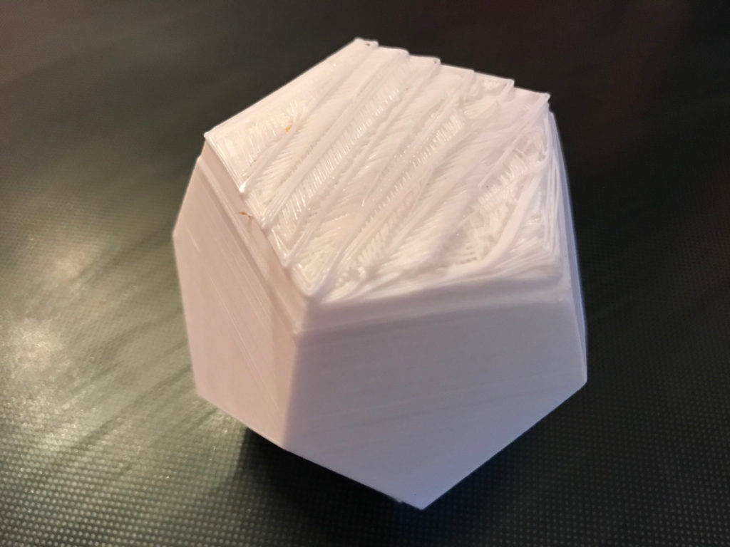
Problem: It’s not uncommon for your 3D model to get moved around or shifted on the print bed in your slicer’s 3D viewer, especially when you’re just learning your way around the adjustment/movement tools. As you can see in Figure 5, the bottom of this succulent pot is uneven and rough in texture. This was caused by the corner of the pot tilted below the print bed.
Solution: The easiest way to correct this issue is to find it before printing. Always take the time to preview your slicing results during the slicing process. Fixing issues before the printing begins will save you time and money.
Loss of Bed Adhesion
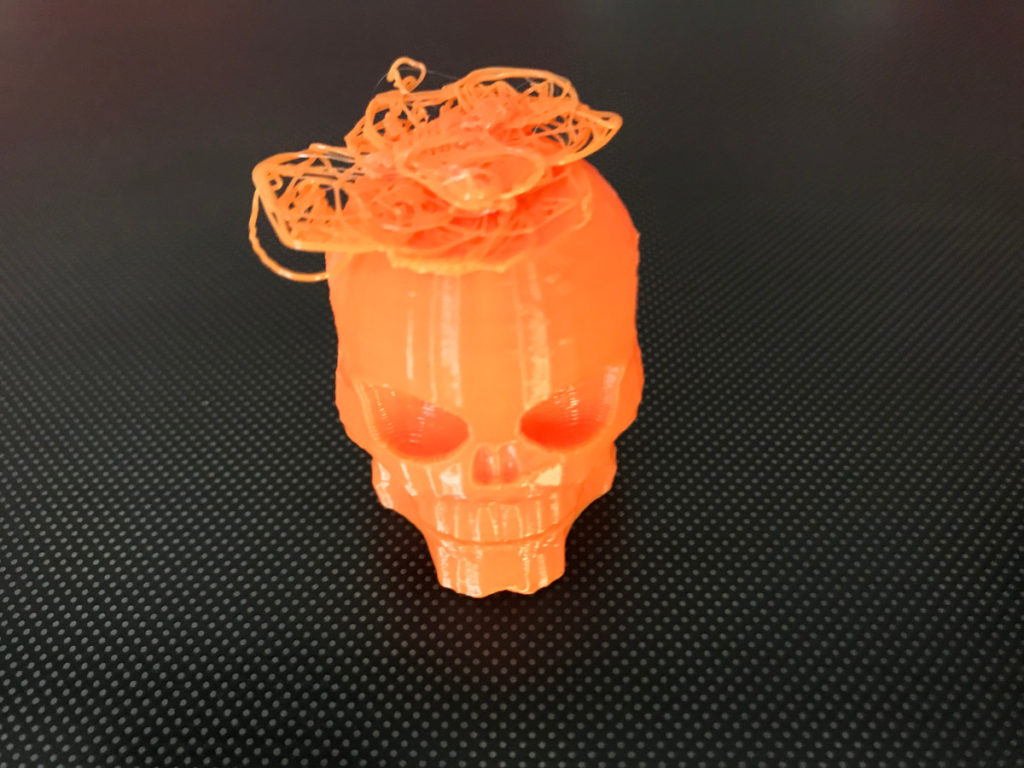
Problem: As you can see in Figure 6, this skeleton head had a slight problem at the end of the printing process. Although the size of the skeleton head may look large enough for decent bed adhesion, the jawbones at the bottom taper in, leaving less surface area than you might think. As soon as the printer switched to some rapid back and forth movement, the vibrations dislodged the head from the print bed.
Solution: Modify the print settings in your slicer software to add a brim to your 3D model. The specific brim values will vary depending on your model, but it won’t be long before you figure out what works best for your situation.
Warping
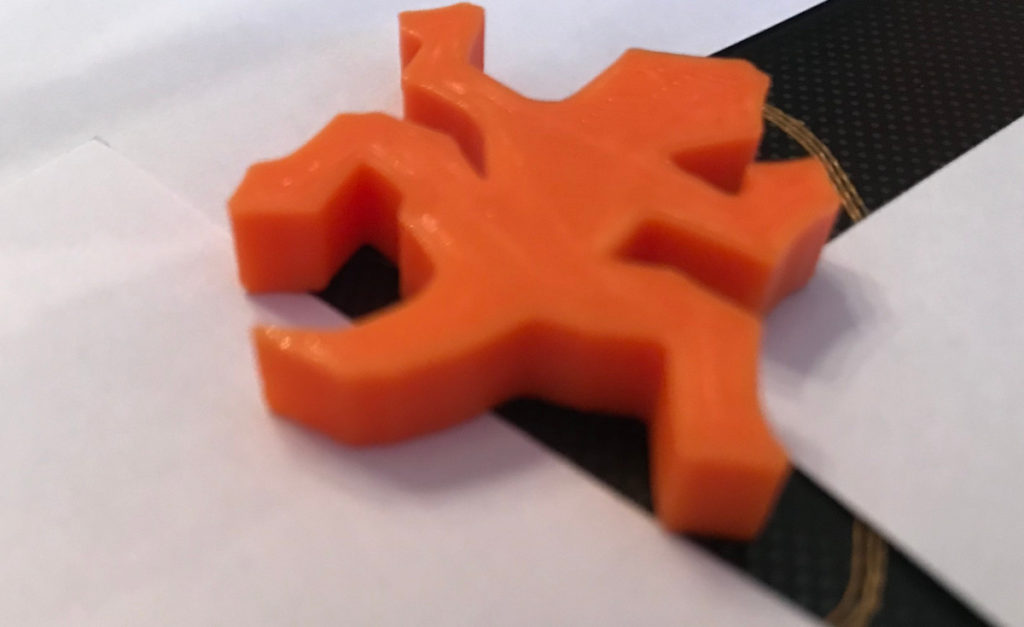
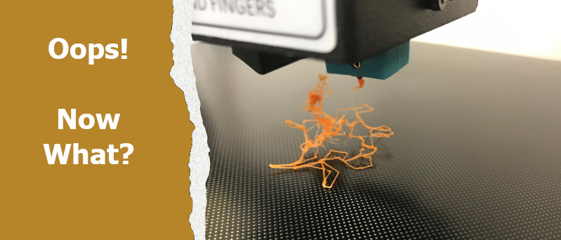
Problem: Warping, which is caused by extruded filament shrinking too much, is evident in Figure 7. Most of the lizard’s appendages detached from our print bed, leaving a large enough gap to slide white cardstock between the bed and the lizard’s tail and feet.
Solution: There are a number of issues that can cause warping to occur, not all of which can be fixed in your slicer’s print settings, and the right solution for you will depend on your specific situation. If you do end up with a 3D model warping, the following checklist can help you find the best solution for your circumstance.
- Make sure your print bed is level.
- Increase the initial layer height and speed in your slicer’s print settings.
- Add a brim to your slicer’s print settings.
- If adding a brim doesn’t stop the warping, you may want to use a raft, which adds a thick section of filament between your 3D model and the print bed. This solution is not always ideal because a raft is harder to remove and uses more filament, but it may be the right solution for your situation.
- You may see recommendations to use a heated print bed, but buying a new bed is not the solution most hobbyists are going to want to try, especially since it’s not guaranteed to solve your specific problem. Our lizard in Figure 7 was printed on a heated bed.
Contact Us
Have you run into a problem that you’re not sure about and you don’t see it listed above? Or have you fixed an issue you’d like to share with fellow readers? If so, feel free to contact us with descriptions and photos. We’ll help you if we can and with your permission, we can add the results of your own troubleshooting endeavor to the growing list of issues above.
We hope our Slicer Software Explained section helped you navigate your way around the slicing process. And we love to hear from our readers, so feel free to contact us anytime to share how your 3D printing journey is going. We can add you to our email list and send you updates as more sections in this series are available.
Our next section, Fun With Fusion 360, will show you how to solve a specific problem by using Fusion 360 to create a new part meant to replace an old broken one.
3D Printing for Beginners Series
- A 3D Printer Overview
- 3D Modeling Options
- Slicer Software Explained
- Fun With Fusion 360
- Toying With Tinkercad
We hope you enjoyed the third segment of our 3D Printing for Beginners series.