A Valentine Paper Circuit Investigation
Paper Circuit Safety Warning
Since our original post, there have been multiple reports of life-threatening injuries to children who have swallowed coin cell batteries. This is a result of the current in the battery causing a chemical reaction that can lead to burns in the esophagus.
Please keep all coin cell batteries and other small parts used in this activity away from young children.
Valentine paper circuits for Valentine’s Day are an excellent way to introduce your kids to the world of electronics. The Valentine templates can be kept simple for the younger kids or made more complex to spark the interest of someone older.
Go Straight to:
Valentine Paper Circuit Step-by-Step Instruction
Printables:
Printable Paper Circuit Tutorial Templates
Printable Valentine Paper Circuit Templates
Note: The circuit tutorial templates need to be printed using landscape orientation. The Valentine paper circuit templates need to be printed using landscape orientation with double-sided, flipped on the short edge.
What Is an Electrical Circuit?
An electrical circuit is a pathway made from a conductive material that electrical current can flow through. You may be familiar with conductive pathways on a printed circuit board, but have you ever seen them on a simple sheet of paper? All you need is some conductive tape, LEDs, and a battery.
Getting Started
Before helping your kids work on their Valentine paper circuit, you should check out our Investigation and Troubleshooting tabs below. Our investigation can save you both time and money, allowing you to have more fun and a little less frustration. You should then help your kids go through our paper circuit tutorials. You can download our tutorial templates, or let your kids draw their own designs using our templates as a guide. Once you and your kids are comfortable with these tutorials, you’re ready to take paper circuits to the next level. Our Valentine paper circuit is a fun way for your kids to start their exploration into the world of electronics.
Supply List
Valentine Paper Circuit Tools & Supplies
| Materials | Tools |
|---|---|
| Paper/Card Stock | Scissors |
| Circuit Templates | |
| Conductive Tape | |
| LEDs | |
| Coin Battery | |
| Foam Tape | |
| Paper Clip (Optional) | |
Note: The cost of this investigation varies with each template, but it ranges from $1.10 – $1.50 per template. Your cost will depend on the number of paper circuits you need to buy supplies for. Buying in larger quantities can lower the overall cost of each paper circuit.
Investigation
Paper Circuit Safety Warning
Since our original post, there have been multiple reports of life-threatening injuries to children who have swallowed coin cell batteries. This is a result of the current in the battery causing a chemical reaction that can lead to burns in the esophagus.
Please keep all coin cell batteries and other small parts used in this activity away from young children.
We created several Valentine paper circuits during our investigation. We checked to see which conductive tape performed best, and which LEDs were our favorite.
Note: As far as batteries were concerned, we continued to use the CR2032 coin cell battery. It performed best during our DIY Hexbug Investigation and it fit our needs for our Valentine paper circuit as well.
Conductive Adhesive Materials
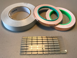
Conductive adhesive allows an electrical charge to flow across the entire surface of the material it’s applied to. During our Valentine paper circuit investigation, we tested the following materials with conductive adhesive:
- Conductive fabric cloth adhesive tape
- 1/4″ copper foil tape
- 1/2″ copper foil tape
- Conductive fabric tape patches
The Winner
The 1/4″ copper foil tape from Amazon.
Note: If you choose to use copper foil tape, be sure to purchase rolls that use conductive adhesive. This ensures that both sides of the tape are conductive.
Investigation Results
First, the conductive fabric cloth was easy to work with, unfortunately, the adhesive was on both sides of the cloth.
Second, we purchased the fabric tape patches to attach the LED legs to the copper tape. Although the patches worked as planned, we decided to use additional strips of copper tape instead. This kept the list of needed supplies down and you should have plenty of extra copper tape.
Third, if you already have copper tape without conductive adhesive or purchased the wrong type by mistake don’t panic. Fold over a small section of the copper tape at the end so the adhesive sides touch. This creates a flap that is conductive on both sides. Use scotch tape to attach the flap to an LED, battery, or the next piece of copper tape. This should work wherever you need a connection.
Fourth, the copper tape will twist and curl onto itself if you peel the backing off all at once. We found it easier to peel the backing off as we applied the tape to the template instead.
Fifth, we chose the 1/4″ copper tape. It was more cost-effective, and the thinner strips were easier to work with when the LEDs were close together. If you find a better deal on 1/2″ tape, it’s easy to cut in half lengthwise.
LEDs
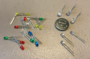
Light-emitting diodes (LEDs) come in a variety of colors and sizes. We tried the 3mm and 5mm two-legged bulbs because they didn’t require any soldering which kept our projects simple. Our case of assorted LEDs included red, yellow, green, blue, and white bulbs. The clear bulbs by the coin cell battery are flashing RGB (red, green, blue) bulbs which were bought separately.
The Winner
The 3 mm LEDs from Amazon.
Investigation Results
First, the 5mm LEDs were a little too big for our needs but you may want to keep some handy for future projects.
Second, LED polarity does matter. The LED’s positive leg must attach to the battery’s positive side, and its negative leg to the negative side.
Note: We used permanent markers to color the LED’s positive leg red and its negative leg black. This can save you time when you’re helping a larger group of kids troubleshoot their circuits.
Troubleshooting
Murphy’s Law – “Anything that can go wrong will go wrong”
And with this project, there are a few areas that will undoubtedly go wrong sooner or later. We’ve composed a list of tips for you to check out if your LEDs don’t light up.
1. Battery
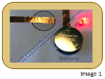
1.1 Make sure the battery has been attached to the foam tape with the positive side up and the foam tape is located on the gray circle below the dotted line marked with a ‘-‘ sign.
1.2 Make sure the battery is working. Attach a spare LED onto the battery with the positive and negative legs in the correct position. If the spare LED lights up, you’ll know the battery is working (Image 1).
Note: Since we first wrote this post, there have been multiple reports of life-threatening injuries to children who have swallowed coin cell batteries. This is a result of the battery causing a chemical reaction leading to burns in the esophagus. Please keep all coin cell batteries away from young children.
2. LED
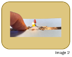
2.1 Fold the corner of your circuit so the battery touches the gray circle on the opposite side of the dotted line and clamp it with a paper clip. Find a spare LED that works and use it to test the circuit where any unlit LED is located. Touch the positive leg of the spare LED to the positive side of the circuit. Touch the negative leg to the negative side. If the spare LED lights up, you’ll know the original LED was a dud (Image 2).
2.2 If step 2.1 proved there’s an issue with the LED, first check if there’s a good connection. Press the LED legs firmly to the copper tape in the circuit to see if the LED lights up. If it does, you need to create a stronger connection to the copper tape.
2.3 If the LED in the circuit still doesn’t light up, check if the LED legs are in the right position. Use the labels on the circuit template to determine whether the LED legs need to be switched around. If the LED in question still doesn’t light up, you’ll most likely need a new LED.
3. Copper Foil Tape
If both the battery and LED are working, there may be a bad connection with the copper tape. Look for a break or tear in the tape, most likely in one of the corner folds. If you find a tear, you can repair the area by applying another strip of tape over the damaged area.
Note: We didn’t have any issues with the copper tape during our investigation. Most of our issues were with the LED legs in the reverse direction or an upside-down battery.
The following tabs will take you through our step-by-step procedure for building three types of circuits. We found building these circuit tutorials helpful to students, but don’t panic if you’re short on time. Our Valentine paper circuits use parallel circuits only, and the parallel circuit tutorial can be built over the simple circuit. You can save the series circuit tutorial for another day.
Paper Circuit Tutorials
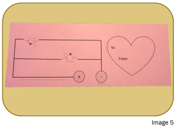
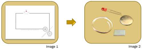
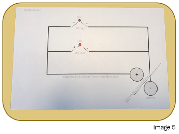
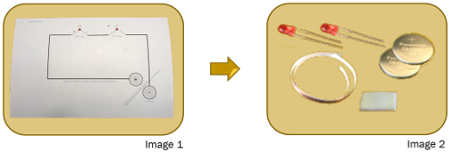
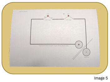
(simple circuit printable instructions) A simple circuit consists of three components: In this simple circuit, the battery is the source of electricity. The copper foil tape creates a conductive pathway. And the LED is the component that needs electricity to work. The battery will act as a switch when you fold the bottom right corner of the circuit along the dotted line. When the battery makes contact with the other side, the circuit will close and turn on the LED. 1.1 Print out the simple circuit template if you haven’t already done so. You will also need an LED, a coin cell battery, a 3/4″ piece of foam tape, and 20″ of copper foil tape with conductive adhesive (Image 1 & Image 2). 2.1 Test your battery and LED. The longer leg of the LED is positive, and the shorter leg is negative (Image 3). You can also use the flat side of your LED to determine which leg is negative as it’s the leg closest to that side. 2.2 Polarity is important with LEDs so be sure to place the positive leg on the positive side of the battery and the negative leg on the negative side. When both the battery and LED are working you should see the LED light up (Image 4). If the LED doesn’t light up, try switching the direction of the LED legs. If it still doesn’t work, you either need a new battery or a new LED. It’s easier to replace a bad battery or LED now before you start the project. Let’s look at the simple circuit template. The solid black line marks the path for the copper foil tape. The small red circle represents the placement of the LED, the dotted lines represent the positive and negative LED legs. The gray circles located in the bottom right corner represent the battery position and the dotted line between them is where the template is folded to complete the circuit (Image 5). 3.2 Attach the 3/4″ piece of foam tape to the gray circle marked negative (‘-‘) in a horizontal direction. Be sure to place the foam tape horizontally or the copper tape in step 3.8 will cover too much of the adhesive surface needed for the battery to stay attached (Image 6). 3.3 Attach the copper tape to the solid black line, peeling the backing off as you go. Don’t remove the backing all at once or the copper tape will twist and stick to itself. Start at the gray circle marked with the ‘+’ sign and follow the black line counterclockwise until you reach the corner (Image 7). 3.4 Corners can be tricky but we’re using copper tape that’s conductive on both sides, so it should be okay if things get a little twisted. 3.5 When you reach a corner the trick is to bend the copper tape in the opposite direction from where you want to go first, creating a diagonal fold (Image 8). 3.6 Hold this folded section in place with your finger as you bend the copper tape back over to continue going in the right direction. You should see a nice corner formed but don’t worry if it’s messy. It gets easier with practice (Image 9). 3.7 Finish placing the copper tape along the solid black line. When you reach the gap use your fingers to cut the tape and then continue placing the tape along the black line on the other side of the gap (Image 10). 3.8 When you reach the end of the black line run the copper tape up and over the piece of foam tape (Image 10). 3.9 It’s time to connect the LED. Bend the LED legs wide enough to connect to the copper tape on both sides of the gap. Line the legs up with the dotted lines and the LED to the red circle (Image 11). Note: Remember that polarity matters. The positive leg needs to connect to the side marked positive. The negative leg needs to connect to the side marked negative. 3.10 Tear off two small pieces of copper tape and use them to cover the LED legs and stick them to the existing copper tape (Image 12). 3.11 Attach the coin battery to the piece of foam tape from step 3.2. Be sure to have the positive side of the battery facing up so it connects to the positive side of the circuit when the corner is folded (Image 13). 3.12 You have just finished building your simple circuit (Image 14). It’s time to fold the template along the crease created at the start in step 3.1 so the battery can complete the circuit. You should now see the LED light up (Image 15). Note: If your LED doesn’t light up, you should check our troubleshooting tips from earlier in the post. You just finished building the simple circuit but what if you need a circuit that uses multiple LEDs? Look at our parallel and series circuits next, two ways to work with multiple LEDs. (parallel circuit printable instructions) A parallel circuit consists of more components than a simple circuit. It still needs a single source of electricity, but it has multiple conductive pathways, one for each LED. During our investigation, we built both parallel and series circuits and while both methods allowed us to use multiple LEDs, we found parallel circuits to be best for our Valentine paper circuits. We found that with a parallel circuit, the current splits as it flows through each pathway while the voltage across each one is the same allowing us to use just a single coin cell battery. You may notice that the parallel circuit is very similar to the simple circuit you just built. Feel free to jump to Step 3.14 if you’re building on top of the simple circuit you just built. Using the completed simple circuit can save you time as well as money on supplies. You can even have your kids sketch in the new pathway and LED position as a fun exercise. 1.1 Print out the parallel circuit template if you haven’t already done so. You will also need 2 LEDs, a coin cell battery, a 3/4″ piece of foam tape, and 26″ of copper foil tape with conductive adhesive (Image 1 & 2). 2.1 Test your battery and LEDs. The longer leg of the LED is positive, and the shorter leg is negative (Image 3). You can also use the flat side of your LED to determine which leg is negative as it’s the leg closest to that side. 2.2 Polarity is important with LEDs so be sure to place the positive leg on the positive side of the battery and the negative leg on the negative side. When both the battery and LED are working you should see the LED light up (Image 4). If the LED doesn’t light up, try switching the direction of the LED legs. If it still doesn’t work, you either need a new battery or a new LED. It’s a lot easier to replace a bad battery or LED now before you start the project. Let’s look at the parallel circuit template. The solid black lines mark the paths for the copper foil tape. The small red circles represent the placement of the LEDs, the dotted lines represent the positive and negative LED legs. The gray circles located in the bottom right corner represent the battery position and the dotted line between them is where the template is folded to complete the circuit (Image 5). 3.1 Bend the bottom right corner of the template inward along the dotted line so the two gray circles touch. Unfold the corner forming a crease on the dotted line. 3.2 Attach the 3/4″ piece of foam tape to the gray circle marked negative (‘-‘) in a horizontal direction. Be sure to place the foam tape horizontally or the copper tape in step 3.8 will cover too much of the adhesive surface needed for the battery to stay attached (Image 6). 3.3 Attach the copper tape to the solid black line, peeling the backing off as you go. Don’t remove the backing all at once or the copper tape will twist and stick to itself. Start at the gray circle marked with the ‘+’ sign and follow the black line counterclockwise until you reach the corner (Image 7). 3.4 Corners can be tricky but we’re using copper tape that’s conductive on both sides, so it should be okay if things get a little twisted. 3.5 When you reach a corner the trick is to bend the copper tape in the opposite direction from where you want to go first, creating a diagonal fold (Image 8). 3.6 Hold this folded section in place with your finger as you bend the copper tape back over to continue going in the right direction. You should see a nice corner formed but don’t worry if it’s messy. It gets easier with practice (Image 9). 3.7 Finish placing the copper tape along the outer solid black line. Ignore the black line that cuts across the circuit near the center for now. When you reach the gap in the black line along the top of the circuit use your fingers to cut the tape and then continue placing the tape along the black line on the other side of the gap (Image 10). 3.8 When you reach the end of this black line run the copper tape up and over the piece of foam tape (Image 10). 3.9 It’s time to connect the first LED so we can test the circuit before adding the second pathway. It will be easier to find a problem in the circuit now before we add more components. 3.10 Bend the LED legs wide enough to connect to the copper tape on both sides of the gap along the top line of the circuit. Line the legs up with the dotted lines and the LED to the red circle (Image 11). Note: Remember that polarity matters. The positive leg needs to connect to the side marked positive. The negative leg needs to connect to the side marked negative. 3.11 Tear off two small pieces of copper tape and use them to cover the LED legs and stick them to the existing copper tape (Image 12). 3.12 Attach the coin battery to the piece of foam tape from step 3.2. Be sure to have the positive side of the battery facing up so it connects to the positive side of the circuit when the corner is folded (Image 13). 3.13 You have just finished building the first pathway in your parallel circuit (Image 14). It’s time to fold the template along the crease created at the start of step 3.1 so the battery can complete the circuit. Once you see the LED light up you will be ready to build the second pathway in the circuit (Image 15). Note: If your LED doesn’t light up, you should check out our troubleshooting tips at the beginning of this post, next to the investigation tab. 3.14 Attach the copper tape to the solid black line that cuts across the center of the parallel circuit. Start on the left side of the line and be sure to overlap the vertical piece of copper tape already in place so a connection is formed. This line is the second pathway to the circuit which turns the simple circuit into a parallel circuit (Image 16). 3.15 When you reach the gap in the second pathway of the circuit use your fingers to cut the tape and then continue placing the tape along the black line on the other side of the gap. 3.16 This second pathway is completed when the copper tape reaches the vertical piece of copper tape on the right side of the circuit. Again, be sure to overlap the two pieces of copper tape so a connection is formed (Image 16). 3.17 It’s time to connect the second LED. Bend the LED legs wide enough to connect to the copper tape on both sides of the gap. Line the legs up with the dotted lines and the LED to the red circle (Image 17). 3.18 Tear off two small pieces of copper tape and use them to cover the LED legs and stick them to the existing copper tape (Image 17). Note: Remember that polarity matters. The positive leg needs to connect to the side marked positive. The negative leg needs to connect to the side marked negative. 3.19 You have just finished building your parallel circuit. It’s time to fold the template along the crease created at the start in step 3.1 so the battery can complete the circuit. You should now see both LEDs light up (Image 17). Note: If your LED doesn’t light up, you should check out our troubleshooting tips again at the beginning of this post, next to the investigation tab. Our Valentine paper circuit only uses parallel circuits so if you don’t have time to go through the series circuit tutorial you are ready to take it to the next level. Have fun with your Valentine paper circuit. (series circuit printable instructions) A series circuit also consists of multiple components that require electricity to work. Unlike the parallel circuit you just built though, these components are located on the same pathway instead of being limited to one component on each. During our investigation, we found that with a series circuit, the current flowing through each part of our circuit was the same, but the voltage was split between them. This meant that we needed more voltage to light two LEDs and had to use two coin cell batteries as the energy source in the circuit below (Our 3 mm red LED had a 1.8 – 2.2 voltage range so two of the LEDs required 3.6 – 4.4 volts). Since each coin cell battery is 3 volts, two of the batteries are necessary for the circuit below). You will notice that this series circuit is also similar to the simple circuit you already built. Even though we’re going to take you through the build instructions step by step your kids are now on their way to becoming experts and should be able to build this circuit quickly and easily. 1.1 Print out the series circuit template if you haven’t already done so. You will also need 2 LEDs, 2 coin cell batteries, a 3/4″ piece of foam tape, and 20″ of copper foil tape with conductive adhesive (Image 1 & 2). 2.1 Test your batteries and LEDs. The longer leg of the LED is positive, and the shorter leg is negative (Image 3). You can also use the flat side of your LED to determine which leg is negative as it’s the leg closest to that side. 2.2 Polarity is important with LEDs, so be sure to place the positive leg on the positive side of the battery and the negative leg on the negative side. When both the battery and LED are working you should see the LED light up (Image 4). If the LED doesn’t light up, try switching the direction of the LED legs. If it still doesn’t work, you either need a new battery or a new LED. It’s a lot easier to replace a bad battery or LED now before you start the project, so these tests are very useful. Let’s look at the series circuit template. The solid black line marks the path for the copper foil tape. The small red circles represent the placement of the LEDs, the dotted lines represent the positive and negative LED legs. The gray circles located in the bottom right corner represent the battery position and the dotted line between them is where the template is folded to complete the circuit (Image 5). 3.2 Attach the 3/4″ piece of foam tape to the gray circle marked negative (‘-‘) in a horizontal direction. Be sure to place the foam tape horizontally or the copper tape in step 3.8 will cover too much of the adhesive surface needed for the battery to stay attached (Image 6). 3.3 Attach the copper tape to the solid black line, peeling the backing off as you go. Don’t remove the backing all at once or the copper tape will twist and stick to itself. Start at the gray circle marked with the ‘+’ sign and follow the black line counterclockwise until you reach the corner (Image 7). 3.4 Corners can be tricky but we’re using copper tape that’s conductive on both sides, so it should be okay if things get a little twisted. 3.5 When you reach a corner the trick is to bend the copper tape in the opposite direction from where you want to go first, creating a diagonal fold (Image 8). 3.6 Hold this folded section in place with your finger as you bend the copper tape back over to continue going in the right direction. You should see a nice corner formed but don’t worry if it’s messy. It gets easier with practice (Image 9). 3.7 Finish placing the copper tape along the solid black line. When you reach one of the gaps in the black line along the circuit use your fingers to cut the tape and then continue placing the tape along the black line on the other side of the gap (Image 10). 3.8 When you reach the end of the black line run the copper tape up and over the piece of foam tape (Image 10). 3.9 It’s time to connect the LEDs. Bend the LED legs wide enough to connect to the copper tape on both sides of the gap. Line the legs up with the dotted lines and the LED to the red circle. Do this for both gaps in the circuit (Image 11). Note: Remember that polarity matters. The positive legs need to connect to the side marked positive. The negative legs need to connect to the side marked negative. 3.10 Tear off small pieces of copper tape and use them to cover the LED legs and stick them to the existing copper tape (Image 12). 3.11 Attach the first coin battery to the piece of foam tape from step 3.2. Be sure to have the positive side of the battery facing up (Image 13). 3.12 Fold a 1 1/2″ piece of the copper tape around on itself, sticky side out, and place it on the battery from step 3.11 (Image 14). 3.13 Attach the second coin battery on top of the first one, using the loop of conductive tape to hold them together. Be sure to keep the positive side of the second battery facing upward as well so it connects to the positive side of the circuit when the corner is folded (Image 15). 3.14 You have just finished building your series circuit (Image 16). It’s time to fold the template along the crease created at the start in step 3.1 so the batteries can complete the circuit (Image 17). Note: If your LEDs don’t light up you should check out our troubleshooting tips at the beginning of this post, next to the investigation tab. (printable Valentine paper circuit instructions) As we walk you through our Valentine paper circuit procedure, the directions will sound familiar. We decided not to skip over any steps even though you’re a pro at them by now just in case you prefer your kids go through the process independently. During our investigation, we designed several templates you can use so feel free to download as many as you’d like. Another option is to help your kids design cards of their own. 1.1 Print out your favorite Valentine paper circuit template if you haven’t already done so. You will also need 2 LEDs, a coin cell battery, a 3/4″ piece of foam tape, and around 25″ of copper foil tape with conductive adhesive (Image 1 & 2). 2.1 Test your battery and LEDs. The longer leg of the LED is positive, and the shorter leg is negative (Image 3). You can also use the flat side of your LED to determine which leg is negative as it’s the leg closest to that side. 2.2 Polarity is important with LEDs so be sure to place the positive leg on the positive side of the battery and the negative leg on the negative side. When both the battery and LED are working you should see the LED light up (Image 4). If the LED doesn’t light up, try switching the direction of the LED legs. If it still doesn’t work you, either need a new battery or a new LED. It’s a lot easier to replace a bad battery or LED now before you start the project, so these tests are very useful. Let’s look at the back of your Valentine paper circuit. It should look familiar as it’s using a parallel circuit design. The solid black lines mark the paths for the copper foil tape. The small red circles represent the placement of the LEDs, the dotted lines represent the positive and negative LED legs. The gray circles located in the bottom right corner represent the battery position and the vertical dotted line between them is where the card is folded to complete the circuit (Image 5). 3.1 Fold your card in half along the dotted line so the circuit image is on the inside (Image 6). 3.2 Carefully poke two holes through the front of the card where the LEDs are located. The holes need to line up with the small red circles that are part of the circuit on the inside of the card. It may be easier to poke from the inside out (Image 7). Note: You may want to push the extra card material back through the hole towards the inside to clean it up a little when you’re done. 3.3 Attach the 3/4″ piece of foam tape to the gray circle marked negative (‘-‘) in a horizontal direction. Be sure to place the foam tape horizontally or the copper tape in step 3.9 will cover too much of the adhesive surface needed for the battery to stay attached (Image 8). 3.4 Attach the copper tape to the solid black line, peeling the backing off as you go. Don’t remove the backing all at once or the copper tape will twist and stick to itself. Start at the gray circle marked with the ‘+’ sign and follow the black line counterclockwise until you reach the corner (Image 9). 3.5 Corners can be tricky but we’re using copper tape that’s conductive on both sides, so it should be okay if things get a little twisted. 3.6 When you reach a corner the trick is to bend the copper tape in the opposite direction from where you want to go first, creating a diagonal fold (Image 10). 3.7 Hold this folded section in place with your finger as you bend the copper tape back over to continue going in the right direction. You should see a nice corner formed but don’t worry if it’s messy. It gets easier with practice (Image 11). 3.8 Finish placing the copper tape along the outer solid black line. Ignore the black line that cuts across the circuit near the center for now. When you reach the gap in the black line along the top of the circuit use your fingers to cut the tape and then continue placing the tape along the black line on the other side of the gap (Image 12). 3.9 When you reach the end of this black line run the copper tape up and over the piece of foam tape (Image 12). 3.10 It’s time to connect the first LED so we can test the circuit before adding the second pathway. It will be easier to find a problem in the circuit now before we add more components. 3.11 Bend the LED legs wide enough to connect to the copper tape on both sides of the gap along the top line of the circuit. Line the legs up with the dotted lines and the LED to the red circle (Image 13). Note: Remember that polarity matters. The positive leg needs to connect to the side marked positive. The negative leg needs to connect to the side marked negative. 3.11 Tear off two small pieces of copper tape and use them to cover the LED legs and stick them to the existing copper tape (Image 14). 3.12 Attach the coin battery to the piece of foam tape from step 3.2. Be sure to have the positive side of the battery facing up so it connects to the positive side of the circuit when the corner is folded (Image 15). 3.13 You have just finished building the first pathway in your parallel circuit. It’s time to fold the template along the crease created at the start of step 3.1 so the battery can complete the circuit. Once you see the LED light up you will be ready to build the second pathway in the circuit (Image 16). Note: If your LED doesn’t light up you should check out our troubleshooting tips at the beginning of this post, next to the investigation tab. 3.14 Attach the copper tape to the solid black line that cuts across the center of the parallel circuit. Start on the left side of the line and be sure to overlap the vertical piece of copper tape already in place so a connection is formed. This line is the second pathway to the circuit which turns the simple circuit into a parallel circuit (Image 17). 3.15 When you reach the gap in the second pathway of the circuit use your fingers to cut the tape and then continue placing the tape along the black line on the other side of the gap. 3.16 This second pathway is completed when the copper tape reaches the vertical piece of copper tape on the right side of the circuit. Again, be sure to overlap the two pieces of copper tape so a connection is formed (Image 17). 3.17 It’s time to connect the second LED. Bend the LED legs wide enough to connect to the copper tape on both sides of the gap. Line the legs up with the dotted lines and the LED to the red circle (Image 17). Note: Remember that polarity matters. The positive leg needs to connect to the side marked positive. The negative leg needs to connect to the side marked negative. 3.18 Use two small pieces of copper tape to cover the LED legs and stick them to the existing copper tape (Image 17). 3.19 You have just finished creating your Valentine paper circuit. It’s time to fold the paper along the crease created at the start in step 3.1. The battery completes the circuit and the LEDs light up (Image 18). 3.20 You can also poke the LED bulbs through the holes from step 3.2 for a brighter look (Image 19). Note: If your LED doesn’t light up, use our troubleshooting tips, next to the investigation tab. Thank you for checking out our Valentine Paper Circuit investigation. We hope you join us again as we continue to delve into the world of paper circuits.Simple Circuit
Step 1 – Supplies
Step 2 – Testing

Step 3 – Build
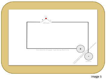

3.1 Bend the bottom right corner of the template inward along the dotted line so the two gray circles touch. Unfold the corner forming a crease on the dotted line.Parallel Circuit
Step 1 – Supplies
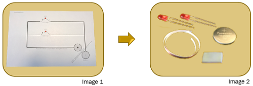
Step 2 – Testing

Step 3 – Build

Series Circuit
Step 1 – Supplies
Step 2 – Testing

Step 3 – Build

3.1 Bend the bottom right corner of the template inward along the dotted line so the gray two circles touch. Unfold the corner forming a crease on the dotted line.Valentine Paper Circuit
Step 1 – Supplies

Step 2 – Testing

Step 3 – Build
