Christmas paper circuits are a fun way to prepare for the holidays. Help your kids use our template or let them create their own using our tutorials below.
(printable template)
(printable instructions)
(Note: Our Christmas paper circuits pop-up Christmas card template needs to be printed using landscape orientation with double-sided printing, flipped on the short edge.)

Are you in charge of your kid’s class party this holiday season?
Are you looking for an easy activity to do with a group of kids at the neighborhood Christmas party?
Building our Christmas paper circuits pop-up Christmas card with your kids can be an exciting way to mix an electronics STEM activity and the holidays. If you and your kids are paper circuit newbies, we recommend you check out our paper circuit tutorial from our Valentine Paper Circuit Mystery investigation. If your kids love to know how things work, we discussed paper circuit switches and sensors in our follow up investigation, The Case of the Missing Easter Eggs.
Our paper circuit review may sound familiar to you from our previous investigations. If it does, feel free to go straight to our building instructions.
Christmas Paper Circuits Procedure

Paper Circuits Review
An electrical circuit is a pathway made from a conductive material that electrical current can flow through. You may be familiar with conductive pathways on a printed circuit board, but have you ever seen them on a simple sheet of paper? Our paper circuits use conductive copper tape for the pathway, LEDs as the component(s) that use the electricity, and a coin cell battery for the power source.
We’ve talked about three types of circuits in the past – simple, parallel, and series.
A simple circuit consists of just three components – the source of the electricity, a single conductive pathway, and a single component that needs the electricity to work.
A parallel circuit consists of more components than a simple circuit. It still needs a single source of electricity, but it has multiple conductive pathways, one for each component requiring electricity to work. If one of the LEDs in our parallel paper circuit stops working, the other LEDs will continue to work. This is because the other pathways in our circuit still have a direct path from the negative side of our battery to the positive side.
A series circuit also consists of multiple components that require electricity to work. Unlike the parallel circuit though, these components are located on the same pathway instead of being limited to one component on each.
During our investigations, we found that the current flowing through each part of our series paper circuit was the same, but the voltage was split between them. This meant that we needed more voltage to light two LEDs and had to use two coin cell batteries as the energy source, instead of one.
Switches and Sensors
A switch is the part of the circuit designed to open and close a gap in the circuit’s conductive path. When the switch closes the gap, the circuit is complete, and the electric current will flow. When the switch opens the gap though, the circuit is incomplete, and the electric current is unable to flow through the circuit.
A sensor is like a switch, but it will only turn on under specific conditions, for example, pressure.
Note: Our Christmas paper circuits pop-up Christmas card uses a parallel circuit with a pressure sensor to control the flow of electricity.
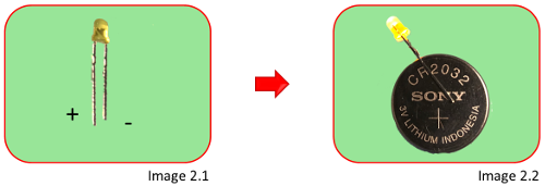
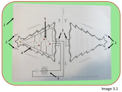
Note: Our Christmas paper circuits pop-up Christmas card will cost just over a dollar, depending on the cost of the supplies at the time. Keep in mind that your upfront costs will vary depending on the number of circuits you’re building, what cardstock you have handy, and whether you must buy ink for your printer. The more you can purchase upfront, especially with the batteries, the cheaper the overall cost per card will be. Since our Christmas paper circuits pop-up Christmas card uses the same materials as we used in our original paper circuit investigation, we’re including the same results below. We continue to use the CR2032 3V coin cell battery. We first investigated this battery with two others during our Case of the Vibrating BrushBot Investigation. It best fit our needs then, and it best fits our needs now. The SONY CR2032 3V coin cell battery from Amazon. Note: We go through quite a few of the CR2032 coin cell batteries. We started purchasing them from Amazon in 20 pcs packs, until we found a seller that offered them in 50 pcs packs for an even better price. We haven’t had any problems with the SONY bulk packs yet but read the Amazon reviews carefully. Not everyone has been as lucky, although it may depend on what you need to use the battery for. Conductive materials allow the electrical charge to flow across the entire surface of the material. During our investigation, we played with conductive fabric cloth adhesive tape, 1/4″ copper foil tape, 1/2″ copper foil tape, and conductive fabric tape patches. The 1/4″ copper foil tape from Amazon. Note: If you choose to use the copper foil tape be sure to purchase rolls that use conductive adhesive. This ensures that both sides of the tape are conductive. We purchased the fabric tape patches to attach the LED legs to the copper tape. Although the patches worked as planned, we decided to use additional strips of the copper tape instead. This kept the list of needed supplies down and you should have plenty of extra copper tape. If you already have copper tape without conductive adhesive or purchased the wrong tape by mistake don’t panic. Fold over a small section of the copper tape at the end so the adhesive sides touch creating a flap that is conductive on both sides. Once you have this flap you can use scotch tape to attach it to an LED, battery, or the next piece of copper tape in your design. This should work wherever you need a connection. Both the 1/4″ and 1/2″ copper tape will twist and curl onto itself if you peel off the backing all at once. We found it easiest to peel off the backing as we applied the tape to the template instead. We chose the 1/4″ copper tape because it was more cost-effective when we bought it and the thinner strips were easier to work with when a design had LEDs close together. If you find a better deal on 1/2″ tape, it’s easy to cut in half lengthwise. Light-emitting diodes (LEDs) come in a variety of colors and sizes. We tried both the 3mm and 5mm two-legged bulbs because they didn’t require any soldering which helped keep our projects simple. As you can see, they come in red, yellow, green, blue and white bulbs and the clear bulbs by the coin cell battery in the picture above are flashing RGB (red, green, blue) bulbs which are perfect for our Christmas tree circuit. The 3 mm LEDs from Amazon. LED polarity does matter, and the LED will only work when the positive (long) leg is attached to the positive side of the battery and the negative (short) leg is attached to the negative side of the battery. Note: We used permanent markers to color the positive legs red and the negative legs black. Once your kids bend the legs to use in their circuits it can be easy to forget which leg is which. Murphy’s Law – “Anything that can go wrong will go wrong” And with paper circuits, there are a few areas that will undoubtedly go wrong sooner or later. We’ve composed a list of tips for you to check out if your LEDs don’t light up. 1.2 Make sure the two thin strips of foam tape are placed in the areas marked ‘foam tape’ on both sides of the light gray circle. If the foam tape is located within the circle, they could prevent a good connection between the copper tape and battery when the push sensor is pressed (Image 1, bottom left arrow). 1.3 Make sure the copper tape that runs up the side, and across the top of the battery does not touch the copper tape under the battery. If these two pieces of tape touch you could get a short circuit (Image 1, bottom right arrow). 1.4 Make sure the battery is working. Slide a spare LED around the sides of the battery making sure the positive and negative legs are in the correct position. If the spare LED lights up, you’ll know the battery is working and is not the issue (Image 2). 2.1 Press down firmly on the battery until the battery makes contact with the copper tape below it. While pressing the battery, use the spare LED to bridge each LED gap where an LED did not light up. Touch the positive leg to the positive side of the circuit and the negative leg to the negative side of the circuit. If the spare LED lights up, you’ll know the original LED is the problem (Image 3). 2.2 If step 2.1 proved there’s an issue with the LED, press the LED legs firmly to the copper tape in the circuit to see whether the LED lights up. If it does, you need to create a tighter connection to the copper tape. Firmly press the layers of copper tape together to see if that helps. 2.3 If step 2.2 doesn’t light up the LED, check to see if the LED legs are in the proper position. If the LED still doesn’t light up, you will most likely need a new LED. If both the battery and LED are working, there may be a bad connection with the copper tape. Look for a break or tear in the tape, most likely in one of the corner folds. If you find a tear you can repair the area by applying another strip of tape over the damaged area. Note: We have not had any issues with the copper tape during our investigations. Most of our issues were with the LED legs in reverse direction or an upside-down battery. As we mentioned during our investigation summary, one option is to use permanent markers to color the positive LED legs red and the negative LED legs black to prevent reversed leg positioning. (printable template) Our Christmas paper circuits pop-up Christmas card template uses a parallel circuit. The LEDs in this circuit will only need a single source of electricity because each LED has a conductive pathway of its own within the circuit. 1.1 Our pop-up Christmas card design uses two sheets of cardstock, one for the background, and one for the Christmas tree paper circuit that will pop up when you open the card. You need to print your circuit template using landscape orientation with double-sided printing, flipped on the short edge. Image 1.1 above shows the front and back of the template printed separately only to show you what both sides look like. 1.2 You will also need a yellow LED for the star, 3 flashing LEDs for the decorations, a coin cell battery, a 1/2″ piece of foam tape, double sticky tape or a glue stick to secure the two pieces of cardstock together, and around 40″ of copper foil tape with conductive adhesive (Image 1.2). 2.1 Test your battery and LEDs. The longer leg of the LED is positive, and the shorter leg is negative (Image 2.1). You can also use the flat side of your LED to determine which leg is negative as it’s the leg closest to that side. We had a hard time finding the flat side during our investigation, so we prefer to look at the leg length when testing. 2.2 Polarity is important with LEDs so be sure to place the positive leg on the positive side of the battery and the negative leg on the negative side. If both the battery and LED are working, you should see the LED light up (Image 2.2). If the LED doesn’t light up, try switching the direction of the LED legs. Still having trouble? You either need a new battery or a new LED. It’s a lot easier to replace a bad battery or LED now before you start the project, so these tests are very useful. If you haven’t already done so, print out the pop-up Christmas card circuit template on the cardstock your kids have chosen for the inside of their card. Note: If your kids would like to color the front of their tree, they should do that now. 3.1 Let’s take a closer look at the circuit. The gray dotted line along the outside of the circuit template is an optional cutting area. If your kids would like to see a red border around the inside of their card, then they should cut along this dotted line (Image 3.1, Arrow 1). 3.2 The gray dotted lines, marked with scissors, that surround the Christmas trees, should be cut until you reach the tree trunk. Do NOT cut the trunks, they need to be folded upward later (Image 3.1, Arrow 2). 3.3 The pressure sensor, located at the power source, consists of two thin strips of foam tape that act as spacers to keep the circuit open until your kids press the battery firmly enough to connect with the copper tape below it, closing the circuit. When pressed, the negative side of the battery will connect with the copper tape below it. The positive side of the battery will already be connected to the copper tape pathway from the top, so no other steps will be needed to close the circuit and light the LEDs (Image 3.1, Arrow 3). 3.4 The solid black lines mark the paths for the copper tape (Image 3.1, Arrow 4). 3.5 The three red circles, and the one yellow circle represent the placement of the LEDs, with the attached dotted lines showing the position of the positive and negative LED legs (Image 3.1, Arrow 5). You’re now ready to help your kids build their pop-up Christmas card. 3.6 Hold the sheet of cardstock you chose for the outside of your card in a landscape position, then fold it in half (Image 3.2). 3.7 If you want to see a border around the inside of your card, cut along the outer gray dotted line on the sheet of cardstock for the inside of the card now (Image 3.3). 3.8 Fold the sheet of cardstock for the inside of the card, keeping the decorated trees on the outside (Image 3.4). Note: Be sure to help your kids with this step. Just in case the template doesn’t print in the exact center of their paper, make sure the two stars, on top of the trees, line up when they fold the inside of the card. 3.9 Cut along the dotted lines that surround the two trees in a triangular shape (Image 3.5). Note: Make sure you don’t cut the tree trunks. 3.10 Fold the trees upward, at the base of the trunk, before the copper tape is added, then unfold them. This will make folding the card easier later (Image 3.6). 3.11 The decorated tree side of the cardstock is the back and needs to be taped or glued to the sheet of cardstock you’re using for the outside of your card. Make sure to apply the adhesive on the four corners (Image 3.7, arrows 1-4) and the long strip in the center, from top to bottom (Image 3.7, arrow 5). 3.12 Carefully turn the inside sheet of cardstock over, center it as you go, and firmly press the adhesive to the back (Image 3.8). Note: We preferred the double sticky tape during our investigation, but your kids need to be careful as they attach the two sections together. The tape doesn’t allow second chances. 3.13 Attach two small slivers of foam tape to the rectangle boxes located on either side of the gray circle. Be sure to stay within the areas marked. If the spacers are placed inside the circle area, they could interfere with the pressure sensor (Image 3.9) Note: During our investigation, we found that if you remove the backing all at once the copper tape will twist and stick to itself. 3.15 Corners can be tricky but we’re using copper tape that’s conductive on both sides. A little twist in the tape at the corners should be just fine. 3.16 When you reach a corner the trick is to bend the copper tape in the opposite direction from where you want to go first, creating a diagonal fold (Image 3.11). 3.17 Hold this folded section in place with your finger as you bend the copper tape back over the fold to continue going in the right direction. You should see a nice corner formed but don’t worry if it’s messy. It gets easier with practice (Image 3.12). Note: We found it easier to create cleaner corners by removing the excess white backing material before we folded the corners. 3.18 Continue placing the copper tape along the path formed by the black line. Make sure the section of copper tape heading towards the tree trunk is over as close to the tree as possible, without attaching to the triangular section that was cut earlier (Image 3.13). Note: You need room for the copper tape as it comes back to the battery to complete the circuit. 3.19 When you reach the gap for the yellow LED, at the top of the star, use your fingers to cut the tape and then continue placing the tape along the black line on the other side of the gap (Image 3.14). 3.20 As you continue attaching the tape, make sure the section of tape below the tree, as you return to the battery, does NOT touch the tape from earlier (Image 3.15) 3.21 Stop attaching the copper tape when you reach the end of the outer black line where you see the Battery label (Image 3.16). 3.22 Place the battery, positive side up, on the two foam spacers. Make sure the battery is centered over the gray circle (Image 3.17). 3.23 Continue running the copper tape along the dotted black line, and across the battery to its far edge. Be sure to stop at the edge so it doesn’t touch the copper tape from the beginning of the circuit (Image 3.18). Note: If this end of the copper tape touches the section of copper tape under the battery it will short circuit. 3.24 You just completed the pressure sensor and power source. It’s time to connect the first LED to the gap along the outer pathway. It’s easier to troubleshoot a problem in the circuit now before additional pathways are added. 3.25 Bend the LED legs wide enough to connect to the copper tape on both sides of the gap, line the legs up with the dotted lines and the LED to the yellow circle (Image 3.19). Note: Remember that polarity matters. The positive leg needs to connect to the side marked positive and the negative leg needs to connect to the side marked negative. 3.27 Press the battery firmly against the bottom of the card. Once you see the yellow LED light-up you will be ready to build the other three pathways in the circuit. Note: If your LED doesn’t light up, you should check out our troubleshooting tips at the beginning of this post, next to the investigation tab. 3.28 Attach the copper tape to the remaining three pathways that cut through the circuit. Be sure to overlap the piece of copper tape already in place so a connection is formed. Run the copper tape down along each black line. When you reach the gap in each pathway use your fingers to cut the tape and then continue placing the tape along the black line on the other side of the gap. Each pathway is complete when the copper tape overlaps the copper tape along the outside of the circuit (Image 3.21). 3.29 It’s time to connect the other three LEDs. Bend the LED legs wide enough to connect to the copper tape on both sides of the gaps, line the legs up with the dotted lines and the LEDs to the red circles, one LED per pathway. Note: Remember that polarity matters. The positive leg needs to connect to the side marked positive and the negative leg needs to connect to the side marked negative. Tear off two small pieces of copper tape and use them to cover the LED legs and stick them to the existing copper tape (Image 3.22). 3.30 Fold the trees up and attach them with tape or glue along the top edge (Image 3.23). 3.31 Press the battery firmly so that it makes contact with the copper tape below it and watch your LEDs light up and flash (Image 3.24) Now that you have a working circuit you may want to use some scotch tape to secure the LED bulbs to the template. You can also poke a small hole through the template near each LED if your kids would like the LEDs to shine a little brighter from the outside of the tree. Congrats, you just finished creating your Christmas paper circuits pop-up Christmas card. Close the card, decorate the front, and enjoy! Supply List
Materials Tools
Card Stock Scissors
Pop Up Christmas Tree Template
Coin Cell Battery
LEDs
Foam Tape
Copper Foil Tape
Double Sticky Scotch Tape/
Glue Stick
Investigation
Battery

The Winner
Conductive Materials

The Winner
Investigation Results
![]() The conductive fabric cloth was easy to work with, but not what we needed, because we only wanted one side of the material to have adhesive.
The conductive fabric cloth was easy to work with, but not what we needed, because we only wanted one side of the material to have adhesive.![]()
![]()
![]()
![]()
LEDs

The Winner
Investigation Results
![]() The 5mm LEDs were a little too big for our needs but you may want to keep some handy for future projects.
The 5mm LEDs were a little too big for our needs but you may want to keep some handy for future projects.![]()
Trouble Shooting
1. Battery
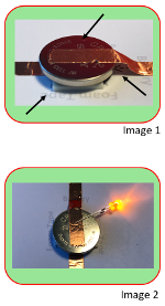 1.1 Make sure the battery has been attached to the foam tape with the positive side up. If the copper tape is covering the ‘+’ symbol, you should still be able to see other markings. The coin cell batteries we’ve used have all had the markings on the positive side of the battery only (Image 1, top arrow).
2. LEDs
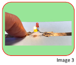 Note: Bend the legs of the working LED from step 1.4 above outward enough to bridge the LED gaps in the circuit. Use it below:
3. Copper Foil Tape

Christmas Paper Circuits Pop-up Christmas Card
(printable instructions)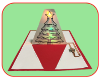 During our investigation into building our first pop-up card, we found that we liked the flashing LEDs best for the Christmas decorations hanging on the tree. We used a pressure sensor to turn the LEDs on and off, but your older kids may enjoy experimenting in this area. If so, have them check out our more detailed discussion into paper circuit switches and sensors in our Case of the Missing Easter Eggs post.
Step 1 – Christmas Paper Circuits Supplies

Step 2 – Christmas Paper Circuits Testing
Step 3 – Christmas Paper Circuits Build

3.14 Attach the copper tape to the solid black line, peeling the backing off as you go. Start in the gray circle marked with the ‘-‘ signs and follow the black line toward the right (Image 3.10)
3.26 Tear off two small pieces of copper tape and use them to cover the LED legs and stick them to the existing copper tape (Image 3.20).

